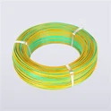
Choosing the correct American Wire Gauge (AWG) size is crucial when purchasing wires and cables for industrial applications involving extreme high temperatures, such as aerospace systems, industrial furnaces, automotive engine compartment electronics, or heating equipment. In high-temperature environments, using overly thin wires can lead to serious insulation failure, equipment shutdown, or catastrophic safety hazards.
This article will introduce how to choose the appropriate AWG wire gauge for high temperature resistant wire, helping procurement teams make wiser purchasing decisions, accurately communicate technical requirements with suppliers, and reduce the risk of improper specification selection or high material costs.
The American Wire Gauge (AWG) is a standardized system for specifying conductor sizes, widely used in the electrical field in North America and also commonly used in international wire and cable procurement.
A basic rule to note is that the smaller the AWG value, the thicker the conductor. For example, the cross-sectional area of a 14 AWG wire conductor is greater than that of a 20 AWG wire.
Under the same conditions, thicker conductors typically have lower resistance and can carry larger currents. Finer conductors may reduce material consumption and installation space, but still must meet the electrical and thermal performance requirements required for the application.
When choosing high temperature resistant wire, AWG wire gauge will directly affect the following important factors:
- Current carrying capacity: The conductor must be able to carry the expected current while ensuring that the operating temperature does not exceed the allowable range.
- Voltage drop: Conductor resistance can affect the actual voltage delivered to the connected equipment.
- Heat generation: Resistors generate heat, which may accumulate continuously in high-temperature environments.
- Installation flexibility: Conductor size and twisting structure can affect wiring, bending, and termination requirements.
- Procurement cost: Thicker conductors typically require more conductive materials, while selecting conductor sizes that are too small may increase reliability and compliance risks.
For buyers, the goal is to avoid unnecessary conductor sizes while meeting electrical, thermal, mechanical, and regulatory requirements, in order to achieve a reasonable balance between performance and cost.
Key Factors to Consider When Selecting AWG Size
Required Current and Electrical Load
The expected load current is the starting point for wire sizing. Higher current generally requires a larger conductor because resistance-related heating increases with current.
For a resistive conductor, heat generation is proportional to the square of current multiplied by resistance:
P = I²R
Where:
- P = power dissipated as heat
- I = current in amperes
- R = conductor resistance in ohms
This relationship explains why a small increase in current can cause a substantial increase in heat generation.
When determining the required conductor size, consider continuous operating current, intermittent loads, startup current, duty cycle, and the applicable electrical code. Continuous-load requirements and protective-device sizing must be evaluated under the rules governing the specific installation.
Ambient Temperature and Operating Temperature
High temperature wire is commonly used in environments such as industrial heating equipment, ovens, power supplies, control systems, and machinery operating near heat-generating components.
Two temperatures must be distinguished:
- Ambient temperature: The temperature surrounding the installed wire.
- Maximum conductor temperature: The permitted operating temperature of the conductor and its insulation system under the applicable specification.
A high ambient temperature reduces the temperature difference available for the conductor to dissipate internally generated heat. As a result, the allowable current may need to be reduced.
For example, a wire operating in a 70°C environment has less thermal margin than the same wire operating in a 25°C environment, even if both carry the same current.
Always confirm whether the manufacturer's ampacity data applies to free air, a bundle, a conduit, or another installation condition. Generic ampacity charts should be treated as preliminary references rather than universal design limits.
Insulation Temperature Rating
The insulation material determines important properties such as thermal endurance, electrical insulation performance, chemical resistance, and mechanical durability.
Common high-temperature insulation materials include:
- PTFE: Suitable for applications requiring high thermal resistance, low friction, and broad chemical resistance.
- FEP: Offers chemical resistance, electrical insulation performance, and processing characteristics useful for many industrial wire applications.
- ETFE: Provides a useful combination of mechanical toughness, abrasion resistance, and chemical resistance.
- Silicone rubber: Offers flexibility and is used in applications requiring compliant insulation at elevated temperatures.
The appropriate material depends on the wire's rated operating conditions and environmental exposure. Exact temperature limits vary by product construction, applicable standard, and manufacturer specification.
Important: A higher insulation temperature rating does not automatically authorize a higher current rating. Conductor size, heat dissipation, bundling, terminal temperature limits, and the governing electrical code must also be considered.
Cable Length and Voltage Drop
Long runs result in voltage drops due to conductor resistance. For sensitive high-temp sensors (like thermocouples) or power distribution, keep the voltage drop under 3%. Use larger AWG sizes (lower numbers) for longer distances.


How to Determine the Correct AWG Size Step by Step
Calculate the Required Load Current
Determine the maximum expected operating current based on the equipment's electrical specifications.
For DC loads, a basic calculation is:
I = P / V
Where P is electrical power in watts and V is operating voltage in volts.
For single-phase AC loads, current calculations may need to account for power factor and efficiency. Three-phase systems require the appropriate three-phase relationship.
For motor-driven equipment, heating systems, and other specialized loads, use the relevant design method and applicable code rather than relying solely on a simplified power calculation.
Determine the Actual Operating Environment
Document the highest expected ambient temperature, not just the average room temperature.
Also identify:
- Whether the wire is installed in free air, a conduit, a harness, or a closed enclosure.
- The number of current-carrying conductors grouped together.
- Whether the wire is exposed to radiant heat or nearby hot surfaces.
- Whether vibration, abrasion, chemicals, moisture, or repeated flexing are present.
- Whether the wire operates continuously or intermittently.
These details help determine the appropriate ampacity data and any necessary correction or adjustment factors.
Select a Preliminary AWG Size
Use the applicable ampacity table or manufacturer data to identify candidate conductor sizes.
For installations governed by the US National Electrical Code (NEC), the relevant ampacity tables and correction requirements depend on the installation method, conductor insulation rating, ambient temperature, and number of current-carrying conductors.
Do not use a generic chart as the final selection basis unless its assumptions match the intended application.
Apply Temperature and Installation Corrections
Where required, calculate the adjusted ampacity using the applicable correction and adjustment factors:
Adjusted ampacity = Base ampacity × Temperature correction factor × Applicable adjustment factors
For example, if a reference ampacity is 30 A and the applicable temperature correction factor is 0.82, the temperature-corrected value is:
30 A × 0.82 = 24.6 A
If an additional conductor-bundling factor applies, it must also be included.
This is an illustrative calculation, not a universal rating for a particular AWG size. The final permissible ampacity must satisfy the applicable code, terminal temperature limitations, overcurrent protection requirements, and the manufacturer's product specifications.
Check Voltage Drop
Calculate voltage drop using the actual conductor length, load current, conductor resistance at operating temperature, and circuit configuration.
If the calculated voltage drop exceeds the design limit, evaluate a larger conductor size.
For low-voltage equipment, even a modest absolute voltage drop can represent a significant percentage of the supply voltage.
Confirm mechanical and installation requirements
The electrically suitable conductor may not be the best choice for the physical installation.
Confirm whether the wire needs:
- Fine-stranded conductors for flexibility.
- A compact outside diameter for high-density assemblies.
- Resistance to abrasion or repeated movement.
- Compatibility with the intended terminals and connectors.
- Suitable minimum bend radius and stripping characteristics.
The final wire size should support both electrical performance and practical installation.
Confirm the Complete Wire Specification
Before placing an order, confirm the conductor gauge, conductor material, insulation material, voltage rating, temperature rating, applicable UL style or other required certification, and any special construction requirements.
The AWG number alone is not a complete purchasing specification.
How Conductor Material Affects AWG Selection
Conductor material affects resistance, weight, cost, and suitability for the operating environment.
Silver-Plated Copper Conductors
Silver-plated copper combines a conductive copper core with a silver surface coating. It is used in certain high-temperature, high-frequency, and specialized electronic applications.
Depending on the product construction, it may offer benefits related to surface conductivity, solderability, and performance under specified thermal conditions.
Buyers should confirm plating requirements, conductor construction, temperature rating, and application-specific performance rather than assuming all silver-plated conductors have identical characteristics.
Nickel-Plated Copper Conductors
Nickel-plated copper is used in selected applications requiring improved surface oxidation resistance or compatibility with elevated-temperature environments.
Its electrical resistance and temperature performance depend on the conductor construction and applicable specification. It should be evaluated against the actual operating conditions rather than selected based on plating material alone.
Purchasing recommendation: Compare the complete conductor specification, including material, stranding, resistance, temperature rating, and termination compatibility. Two wires with the same AWG size can perform differently if their construction and installation conditions differ.
Matching AWG Size with High Temperature Insulation Materials
| Insulation material | Key characteristics | Typical application considerations |
| PTFE | High thermal resistance, low friction, broad chemical resistance | Chemical processing equipment, industrial heating systems, demanding electrical assemblies |
| FEP | Chemical resistance, electrical insulation performance, useful processing characteristics | Equipment wiring, instrumentation, and selected high-temperature electrical applications |
| ETFE | Mechanical toughness, abrasion resistance, chemical resistance | Industrial controls, compact assemblies, and applications exposed to mechanical wear |
| Silicone rubber | Flexibility and compliant insulation | Equipment requiring flexible leads and resistance to elevated operating temperatures |
These materials are not interchangeable in every application. Their suitability depends on rated temperature, voltage, mechanical stress, chemical exposure, wall thickness, and applicable product approvals.
When purchasing PTFE, FEP, ETFE, or silicone-insulated wire, request the relevant technical data sheet and confirm that the selected AWG size is available in a construction suitable for the intended operating conditions.
Why choose an experienced high-temperature wire manufacturer?
For OEM original equipment manufacturers, electrical equipment manufacturers, and industrial distributors, choosing wire manufacturers with professional capabilities can help improve the accuracy of specification matching and procurement efficiency.


Zhejiang IRONFLON Wire&Cable Co., Ltd. is a manufacturer driven by research and development, specializing in the production of high-temperature fluoropolymer insulated wires and cables such as PTFE, FEP, and ETFE.
The production facilities of Zhejiang IRONFLON consist of eight independent and complementary production lines. Each production line undertakes specific processing tasks and supports the manufacturing of wire and cable products with different structures through process connections.
The main production processes include:
- Conductor stranded wire: Twist the conductor according to the specified conductor structure requirements.
- Outer conductor braiding: Processing braided shielding layers for applicable cable structures.
- Outer conductor winding: According to the product structure requirements, the corresponding outer conductor structure is formed by winding.
- Core wire cabling and tape wrapping: Combine insulated core wires into cables and perform tape wrapping processing according to product requirements.
- Fluororesin extrusion: Processing fluororesin insulation layer and sheath through extrusion technology.
- Fluororesin Insulated Cold Pushing and Sintering: Suitable cold pushing and sintering processes are used to produce fluororesin insulated wires with corresponding structures.
- Fluororesin film wrapping and sintering: The fluororesin film wrapping and sintering process is used to form the corresponding insulation structure.
The above production facilities cover various methods of manufacturing fluororesin wires and cables. The specific production process route is determined based on the insulation material, conductor design, size requirements, and product application conditions.


Zhejiang IRONFLON provides customized development and manufacturing services for wires and cables, catering to application needs that cannot be fully met by standard products. Based on the technical drawings, product samples, technical specifications, or actual usage conditions provided by customers, we can evaluate and develop corresponding product structures and manufacturing plans.
The customization scope covers conductor materials and twisted structures, conductor specifications, insulation materials, number of cores, shielding structures, sheath forms, product colors, delivery lengths, and packaging methods. Based on product structure and application requirements, the company can evaluate suitable production routes by combining existing conductor processing, weaving, wrapping, extrusion, cold pushing, sintering, and cabling processes.
For projects with clear technical specifications, IRONFLON can carry out OEM production according to the materials, structures, and relevant standards confirmed by the customer. For projects that are still in the development stage, customers can provide application scenarios, functional requirements, and target performance parameters, and both parties can further evaluate the feasibility of product structure, material combination, sample production, and mass production.
Conclusion
Choosing the correct AWG wire gauge for high temperature resistant wire requires consideration of much more than just load current. Engineers and procurement personnel must also comprehensively evaluate current carrying capacity, ambient temperature, insulation temperature resistance level, conductor materials, voltage drop, installation conditions, and applicable standards.
Adopting a systematic selection process can help avoid issues such as insufficient conductor size, unnecessary over selection, excessive voltage drop, and mismatched product specifications.
Are you looking for high temperature resistant wire for the next project?
Welcome to contact us to discuss the AWG wire gauge, insulation material, rated voltage, operating temperature conditions, and specific application requirements you need.