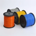
UL10308 single core copper wire, with its rated temperature of 200℃, rated voltage of 600V, and excellent acid and alkali resistance, as well as aging resistance, has become the preferred wire for wiring in electronic devices and high-temperature environmental equipment (such as microwave ovens and industrial instruments). But many purchasers and engineering technicians overlook a key issue: hidden faults such as conductor breakage and poor contact may occur during the production, transportation, or cutting process of wires, which directly affect the safety and service life of equipment operation.
The so-called "continuity testing" simply means checking whether the conductor of UL10308 single core copper wire is complete and without breaks, to ensure that the current can pass smoothly. Seemingly simple detection steps can avoid the risk of equipment short circuit, heating, and even fire in the later stage, especially in harsh working conditions such as high temperature and corrosion. Once the continuity of UL10308 wire is compromised, the loss may far exceed the wire itself. Today's article, combined with professional operating standards, teaches you how to quickly and accurately detect the continuity of UL10308, making it easy for beginners to get started.
Why Do UL10308 Wires Need To Undergo Continuity Testing
Many customers who receive UL certified cables feel that everything is fine and there is no need for further inspection. But to be honest, hidden faults are far more common than we imagine. By sharing a few real situations I encountered, everyone will understand why this step cannot be saved.
Let's talk about the production process first. The conductors of UL10308 are mostly tin plated copper wires, as well as bare copper and silver plated copper. The insulation layer is made of FEP. When drawing, twisting, or wrapping insulation layers, it is easy to cause local breakage of the conductor, or the insulation layer is wrapped too tightly, which can damage the conductor. These problems are not visible to the naked eye, and if not detected, they will only cause chaos when installed in the equipment.
Looking at transportation and storage, when handling wires, a slight force of squeezing or pulling may cause the internal conductor to break; Especially for fine wire gauges such as 32AWG-20AWG, the toughness itself is poor, and the force on the coil is uneven when stacked, with breakpoints being more common. During construction, if the wire is stripped too hard or cut improperly, the conductor may be damaged or not completely removed. The remaining insulation layer can affect conductivity and ultimately lead to equipment failure, which is not worth the loss.
More importantly, UL10308 is commonly used for wiring in fields with extremely high safety requirements such as home appliances, metallurgy and chemical engineering, and automobiles and ships. Once the conductor conductivity is poor, it can cause equipment shutdown, burning, or even safety accidents. So whether it's warehouse acceptance, pre construction, or post maintenance, taking a few minutes to do an inspection can really avoid many risks.


Common Detection Tools, Choose As Needed
Many people think that testing requires professional and expensive equipment, but in fact, it is completely unnecessary. In my daily practice, these three tools are sufficient to cover the vast majority of scenarios, with full cost-effectiveness. Novices can choose according to their own needs.
The most commonly used and easily available one is a digital multimeter, which almost every electrician and engineer has at hand. It is recommended to choose the "beep mode" (the mode with a sound icon, also known as the continuity mode in English), which is very convenient to operate and does not require repeated reading. Here's a reminder: it's best to calibrate before use to ensure accurate test results, otherwise it's easy to misjudge.
If it is a batch inspection, such as screening a large number of wires when entering the warehouse, then a continuity tester is more suitable. It is specifically designed to check the continuity of wires, and the operation is even simpler than a multimeter. After turning on the device, place two probes at both ends of the wire, and when they are connected, a buzzing sound will sound. There is no need to set any parameters, and beginners can quickly get started. The only drawback is that it cannot read the specific resistance value.
There is another situation, such as when the wire is laid for a long time (more than 10meters), or when it is threaded through a pipe or buried underground, and a regular multimeter cannot find the breakpoint, a time domain reflectometer is needed. It emits high-frequency signals, and based on the reflection of the signals, it can accurately locate the breakpoint position with an accuracy of meters. It is suitable for complex industrial scenes.
Core Steps Of UL10308 Continuity Testing
No matter which tool is used, the core is to see if the conductor can form a complete circuit. I usually use a digital multimeter the most. Taking it as an example, I will teach everyone step by step without complicated terminology, just follow the instructions.
Firstly, it is important to prepare in advance, otherwise safety issues may arise. If you are testing wires that have already been installed on the device, be sure to cut off the power first. It is best to use a voltage tester to confirm if there is electricity, to avoid electric shock and protect the testing tool. Then process the wire, strip 5-10mm off the insulation layer at both ends, exposing the tinned copper wire inside. When stripping, do not apply too much force to avoid damaging the conductor. If there are oil stains or oxide layers on the surface of the wire, gently rub it with sandpaper for better contact and more accurate detection results. Finally, calibrate the multimeter, set the gear to the beep mode, and touch the two probes together. If you can hear the beep and the screen displays a resistance close to 0Ω, it means that the multimeter is good; If there is no sound or "OL" displayed, check the battery or replace the multimeter.
Once ready, we can proceed with the formal testing. Touch the red and black probes of the multimeter against the conductors at both ends of the wire, without distinguishing between positive and negative poles. Just stick them tightly, avoiding poor contact or misjudgment. Then look at the result: if you hear a buzzing sound and the screen displays a resistance of ≤ 0.1Ω, it means that the wire conductor is intact and has no breakpoints; If there is no buzzing, the screen displays "OL", or the resistance is much higher than the standard value of the corresponding wire gauge (for example, the resistance of 22AWG far exceeds 56.4Ω/km), it indicates that the wire has a break or poor contact. I am used to checking twice more, such as peeling a small piece of insulation layer in the middle of the wire and testing again, to avoid mistaking good wires for bad ones due to poor local contact.
If the wire material is detected to be non-conductive, the breakpoint position needs to be found. There are two possible scenarios for higher efficiency. If the wire is relatively short, not exceeding 10meters, use the "segmented inspection" method. Starting from one end, peel off a little insulation layer every 1-2meters, and use a multimeter to measure the conductivity at this position and one end. Slowly narrow down the range and quickly find the breakpoint. If the wire is very long, or if it passes through a pipe or is buried underground, use TDR to connect the instrument probe to one end of the wire, set the propagation speed, and the instrument will display the signal reflection waveform. The place where the waveform suddenly changes is the location of the breakpoint, which is accurate and fast.
Don't be careless after the inspection, it's important to do a good ending. Wrap the stripped area with insulating tape to prevent oxidation of the conductor and avoid short circuits. In addition, it is best to keep good records, including the testing date, wire specifications, tools used, testing results, and breakpoint location (if any), which will facilitate traceability in the future. Unqualified wires must be placed separately, marked properly, and not accidentally used on equipment; If the breakpoint is near the end, cut off the damaged part and retest it to be qualified, it can still be used.
Professional Skills: Avoid Common Misconceptions And Achieve More Accurate Detection
Many beginners are prone to misjudgment during testing, which is actually due to neglecting these details. Remember the following tips to make the test results more reliable:
- Neglecting environmental impact: The conductor resistance of UL10308 wire is affected by temperature, and the ambient temperature should be recorded during testing (the standard testing temperature is 20℃). If the temperature deviation is large, the reading should be corrected based on the resistance temperature coefficient to avoid misjudgment caused by high/low temperature;
- Poor contact of probe: If the probe only contacts the tin plating layer on the surface of the conductor during testing, poor contact may be caused by oxidation of the tin plating layer. It is recommended that the probe penetrate deep into the conductor or polish the tin plating layer before testing;
- Confusing "conduction" and "short circuit": This test only determines whether the conductor is conducting or not. If the resistance value is found to be abnormally low (far below 0.1Ω) during testing, further testing is needed to determine whether there is a short circuit (such as damaged contact between the conductor and the insulation layer), in order to avoid potential hazards during later use.
Finally, we would like to remind everyone that the inspection of UL10308 wire should not only focus on "continuity", but also comprehensively judge the quality of the wire based on its conductor specifications and resistance standards. If you encounter complex problems during the inspection (such as long-distance wire breakpoint positioning and low efficiency in batch inspection), you can leave a message for consultation, and we will provide more accurate solutions.