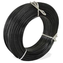
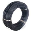
Friends who work in industrial equipment, high-end electronics, or aerospace related fields must be familiar with ETFE insulated wire, right? With its advantages of high temperature resistance, corrosion resistance, and strong insulation, it has become a "hot commodity" in many high-end scenarios. After all, it can work stably in high temperature environments of 200-260 ℃ and withstand various chemical corrosion, which is not comparable to ordinary wires. In my years of working in the wire and cable industry, I have seen too many cases of accidents caused by continuity issues. Even the best ETFE wire, if the internal conductor is broken or poorly connected, the equipment will either strike directly when powered on, and in severe cases, it can also cause safety hazards, resulting in significant losses. Today, let's talk about how to measure the continuity of ETFE insulated wire. Novices can learn from it and basically avoid 80% of the problems.
What is the "continuity" of ETFE insulated wire?
Simply put, the conductor inside the wire must be a complete path from one end to the other, with no breaks, and the current can pass smoothly. This is the qualified continuity. On the contrary, even if there is a slight breakage in the conductor or if the joint is not firmly connected, it is considered a continuity failure.
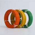
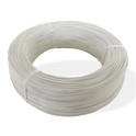
Although the ETFE insulation layer is transparent or semi transparent, even if the conductors inside can be seen, the continuity cannot be judged by the naked eye. Many times, the conductors are "hidden fractures", which may not appear to be broken on the surface but are actually broken inside, and cannot be distinguished by the naked eye. It must be detected by tools.
Moreover, ETFE wires are mostly used in complex scenarios such as high temperature, chemical corrosion, etc. (such as aerospace, industrial equipment, precision instruments), which require higher continuity. Even a small flaw can cause the entire equipment to malfunction, so the connectivity testing process must not be omitted!


Practical methods for detecting continuity
The digital multimeter that I use the most for regular testing is also the most suitable for beginners. As long as this tool is available at home or in the workshop, I can operate it. I usually first set the multimeter to the gear with the "sound icon", which is particularly convenient. As long as there is continuity, it will emit a beeping sound, so you don't have to stare at the dial all the time. Then peel off a small section of insulation from both ends of the wire, being careful not to peel too much, otherwise the conductor is prone to oxidation. After peeling, if there is oil or oxidation on the surface of the conductor, gently polish it with sandpaper. Next, contact the two test probes with the conductors at both ends of the wire, without distinguishing between positive and negative poles, just connect them randomly. If you hear a buzzing sound and the resistance value displayed on the dial is very low, almost close to 0, it means there is no problem with continuity; If there is no sound and the dial displays "OL", it must be a broken conductor that needs to be replaced or repaired as soon as possible. Here is a reminder to everyone that if it is a multi-core ETFE wire, it must be tested core by core. I have missed checking one core wire before, which caused the equipment to operate unstably. It took me a long time to find the problem.
If it is a batch inspection in the workshop, using a multimeter alone would be too time-consuming. At this time, I will use a conductivity tester, which is more accurate and efficient than a multimeter. This instrument does not require complex adjustments. Set the basic threshold when turned on, connect the two ends of the wire to the test interface, press the test button, and within a few seconds, the result will be displayed. A green light indicates qualification, a red light indicates a breakpoint, and the breakpoint location can be roughly located, saving a lot of troubleshooting effort. However, this instrument is suitable for batch testing. For personal or small-scale testing, a multimeter is completely sufficient.
There is also a situation where the multimeter detects a breakpoint but cannot locate the specific location, especially for long-distance ETFE wires or when the insulation layer is not broken but the internal conductor is broken. In this case, a TDR breakpoint locator is needed. This is a professional level tool, and I also learned it from the old technicians in the factory. It is slightly more complicated to operate. If beginners are not familiar with it, I suggest finding a professional to handle it. Its principle is to emit high-frequency signals, which will reflect back when encountering a breakpoint. The instrument can calculate the position of the breakpoint with a very small error, basically no more than 10cm, and can quickly find the problem without having to strip the entire wire for inspection, saving a lot of trouble.
Factors Affecting Continuity
The first issue is the source, which is the quality and processing technology of the wires themselves. I had a customer who used a batch of cheap ETFE wires before, but the conductor material was impure and there were impurities inside. After only a few months of use, there was a hidden fracture. Later, they replaced it with high-quality wires that met the standards, and this problem did not occur again. In addition, the extrusion process of ETFE insulation layer is also crucial. If the temperature control is not good, the insulation layer and conductor are not tightly attached, and the conductor is prone to oxidation and fracture after long-term use. Therefore, when selecting wires, it is necessary to choose manufacturers with mature processing technology.
Next is mechanical damage during installation and use, which is the most common issue. Many workers use force to pull and bend wires during installation in order to catch up with the schedule. Sometimes, the wires are scraped or squeezed by sharp equipment. Although the ETFE insulation layer is strong and appears intact on the surface, the internal conductors may have already broken. When wiring, loose or loose crimping of the joints, or oxidation at the joints, can all lead to continuity failure. Especially in high temperature and vibration scenarios such as industrial equipment, this kind of damage will be more obvious. I suggest that everyone pay more attention when installing, try to avoid pulling and bending, and test the continuity again after wiring to ensure that there are no problems.
Environmental factors cannot be ignored. Although ETFE insulation layer is resistant to high temperature and corrosion, long-term exposure to extreme environments can still cause problems. For example, long-term exposure to strong ultraviolet radiation can cause ETFE materials to age, resulting in microcracks on the surface and oxidation of the conductor, leading to breakpoints; Long term exposure to high humidity and strong corrosion environments can cause conductors to rust and break easily. Even if the insulation layer can withstand corrosion, internal conductors may still have problems. I encountered this situation on a project by the seaside before, but later I added protective covers to the wires, and the situation improved significantly.
Finally, there is the issue of aging and wear, and even high-quality ETFE wires have a lifespan. After long-term use, if the conductor experiences metal fatigue, it is easy to break, and the insulation layer will also age and become brittle, affecting continuity. Especially in high-frequency vibration and repeated bending scenarios, the aging speed of wires will be faster. It is recommended that everyone regularly check and replace the wires that are found to be aging in a timely manner. Do not continue to use them with a lucky mentality.
In fact, in summary, the continuity testing of ETFE insulated wires is not that complicated, and even beginners can quickly get started. The core is twofold: firstly, selecting high-quality wires to avoid problems from the source; The second is to do a good job in daily inspection and maintenance, regularly test, pay attention to installation and use, and avoid pits that are prone to damaging wires.
I have been in the industry for so many years and deeply understand that instead of waiting for equipment strikes or safety hazards to occur before investigating, it is better to spend a few minutes on regular inspections. This is both simple and efficient, as it can extend the service life of wires and avoid unnecessary losses. If anyone encounters difficulties in finding breakpoints, unsure of which tool to choose, or other uncertain issues during testing, they can contact me and we can discuss and exchange ideas together. After all, minimizing pitfalls and saving costs are our most practical needs.